1. Packaging: 1) Wrapped by protective film; 2) Packed in standard wooden cases or carton boxes for international shipping. 2. Shipping: Available via logistics, truck, train, sea, or air, depending on customer preference and destination. 1. Q: Are you a trading company or manufacturer? A: We are an original equipment manufacturer (OEM). Adjustment of the Main Drive Gap of Wheeled Construction Machinery Drive Axle
1. Check and adjust the bearing clearance of the driving bevel gear. The bearing clearance of the driving bevel gear is generally 0.05-010mm. When the clearance exceeds 0.10mm, it should be adjusted: fix the dial indicator on the axle housing, and the contact of the meter is against the driving gear The outer end of the gear shaft, and then axially pry the upper flange of the gear shaft, the absolute value of the maximum and minimum readings of the dial gauge is the bearing clearance; when adjusting, you can increase or decrease the adjustment gasket between the inner ring of the driving gear bearing and the shaft shoulder. If you add a gasket, the bearing becomes loose, and vice versa.
2. Inspection and adjustment of the bearing clearance of the driven bevel gear. The normal clearance of the left and right bearings of the driven bevel gear is 0.05-0.10mm, which can be adjusted by the adjustment rings on both sides of the differential housing. First, remove the lock plate on the adjustment ring, and then twist the two adjustment rings to adjust (the two adjustment rings must be screwed in or out at the same time to ensure the meshing gap and impression of the gear pair); after adjustment, the driven gear should be It is suitable to rotate flexible and have a little resistance, but there is no loose feeling.
3. The adjustment of the thrust screw of the driven wheel loader bevel gear. For construction machinery with thrust screws on the back of the driven gear (such as ZL50 loader), the gap between the end of the thrust screw and the back of the driven gear should be 0.20-0.40mm . When adjusting, first loosen the fixing nut, then tighten the screw and back 1/3 turn, and then lock the fixing nut.
4. Inspection and adjustment of the meshing clearance and impression of the driving and driven bevel gears. Inspection methods and standards: When checking the meshing of the driving and driven bevel gears, the tooth surface of the driving bevel gear is usually coated with red lead oil first. In the case of gear meshing, turn the gear with a little resistance, and then check the traces on the Teeth of the driven gear; when meshing correctly, the contact length of the imprint should be about 2/3 of the full tooth length, and the contact traces are 2-4cm from the small end .(Main Drive,Axle Of Sdlg Loader,Pinion Ring Gear,Wheel Loader Bevel Gear)
Main Drive,Axle Of Sdlg Loader,Pinion Ring Gear,Wheel Loader Bevel Gear Jinan Union Construction Machinery Co., Ltd. , https://www.tfloaderparts.comHigh Pressure Piston Double Fluid Grouting Pump
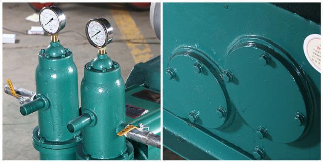
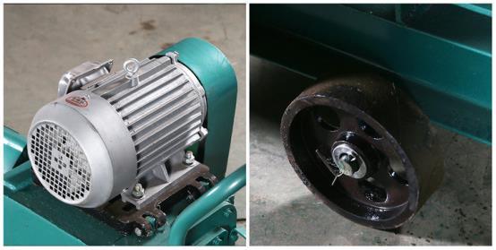
Introduction:
The High Pressure Piston Double Fluid Grouting Pump is a specialized piece of equipment used in construction and mining industries. Also known as a piston pump, it is designed to handle a variety of fluids such as mud, yellow mud, sodium silicate, oil water, and other media. This pump can operate independently or in combination with different materials, making it highly versatile for various applications. It is widely used in tunneling, coal mining, grouting for water plugging, rock and concrete reinforcement, sealing cracks in tunnels, breaking up rock masses, and more. Its applications also include anchoring grouting, backfill grouting, preventing surface subsidence, controlling landslides, and correcting building deflections.
Features:
This high-pressure grouting pump is known for its compact design, reliable performance, and low failure rate. It is easy to clean and maintain, offering high pumping pressure for efficient operation. The machine is built for durability and ease of use, making it an ideal choice for demanding environments.
Model
HIB-3
HJB-6
Motor Capacity
3kW
4kW
Pump Delivery
3m³/h
6m³/h
Maximum Pressure
1.5MPa
3MPa
Cylinder Transfer Pipe Quantity
Single Cylinder
Double Cylinder
Motor Speed
1440r/min
1440r/min
Grouting Pipe
32/38mm
32/38mm
Head of Delivery
Horizontal 20-50m, Vertical ≤20m
Horizontal 20-50m, Vertical ≤20m
Boundary Dimension
1250*430*850
1250*430*850
Weight
250kg
320kg
Packaging & Shipping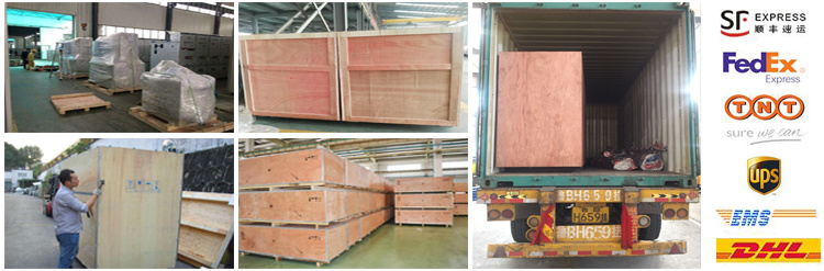
FAQ
2. Q: How long is your delivery time? A: It depends on the model and quantity. Typically, 3-5 days if in stock, and 15-30 days for custom orders.
3. Q: Do you provide samples? Is it free or paid? A: Yes, we can offer a sample machine, but it is not free. You will need to pay for the sample and shipping costs.
4. Q: What are your payment terms? A: We accept T/T, Western Union, MoneyGram, PayPal, Alibaba Escrow, etc. For payments under USD 5000, full payment in advance is required. For larger orders, 30% T/T in advance and the balance before shipment.