The microwave transmission can be understood as simple as this: There are direct waves and reflected waves in the propagation path from the transmitter to the receiver. The oval area under the direct wave is called the Fresnel zone. The odd Fresnel zone differs from the direct wave by an odd number of half wavelengths in succession, but the same phase arrives, which can be a useful supplement to the direct wave. Even Fresnel is just the opposite and can weaken the energy of the direct wave. General design requirements only need the first Finner area.
The Fresnel zone of the radio wave beam is an ellipsoid region that directly surrounds the visible line of sight path. Its thickness will vary depending on the signal path length and the signal frequency.
As shown in the figure above, when a hard object protrudes into the signal path in the Fresnel zone, sharp edge diffraction will deflect some of the signal, causing it to reach the receiving antenna slightly later than the direct signal. Since these deflected signals are out of phase with the direct signals, they reduce their power or cancel them completely. If trees or other "soft" objects protrude into the Fresnel zone, they weaken the signal that passes through (reduces its intensity). In short, despite the fact that you can see a location, this does not mean that you can establish a good wireless microwave link to that location.

A line is connected between the transmitting and receiving antennas. With this line as the axis, there is no blockage of obstacles in a pipe-like area with radius R. This pipeline is called the Fresnel Zone. The Fresnel Zone is an ellipsoid. The transmitting and receiving antennas are located on the two focal points of the ellipsoid. In the figure, R is the first Fresnel radius. The formula is as follows:
R = 0.5 (λD) 0.5 (4) λ is the wavelength and D is the distance between the two antennas λ = 3*108/fm
Taking a wireless bridge as an example, a bridge generally operates in the 2.4-5.8 GHz frequency band, and electromagnetic waves have characteristics similar to light waves. In the short-distance transmission, since the power headroom is large, even if there is a block in the middle, communication can be performed through the reflected wave or the sidelobe of the antenna. However, at long distances, a clear line of sight is required between the transmitting and receiving antennas. The meaning is that there is a line between the transmitting and receiving antennas, and the line is centered on R and the radius is R. In a pipeline-like area, there is no obstruction. As shown in the figure, this pipeline is called the Fresnel Zone, Fresnel Zone is an ellipsoid, and the transceiving antenna is at the two focal points of the ellipsoid. In the figure, R is the first Fresnel radius. The formula is as follows:
R = 0.5 (λD) 0.5 power λ is the wavelength, D is the distance of the two antennas
From the formula, when the frequency is fixed, the Fresnel radius increases with the transmission distance.
Example: When D=10Km, f=2.4GHz, λ=0.125m R=17.678m
When f=5GHz, λ=0.06m R=12.247m
From the above comparison, it can be obtained that when the distance is fixed, the higher the frequency, the smaller the Fresnel radius. This indicates that certain obstacles affecting communications in low-frequency communications may no longer affect communications at high frequencies.
In order to ensure the normal communication of the system, the height of the transceiver antenna must be set so that the obstacles between them do not exceed 20% of the Fresnel zone. Otherwise, the multipath propagation of the electromagnetic wave will have an adverse effect, leading to a decline in the communication quality. Interrupt communication. For example, in maritime communication, where the communication is of the same height, the frequency is 2.4 GHz, the communication distance is 7 Km, and the height of the waves is 2 meters, then the height of the antenna should be greater than L=2+14.790=16.790 m.
From the transmitter to the receiver, there are direct waves and reflected waves in the propagation path. The direction of the electric field of the reflected waves is just opposite to the original and the phase is 180 degrees out of phase. If the antenna height is low and the distance is long, the difference between the direct wave path and the reflected wave path is small, and the reflected wave will have a destructive effect.
In the actual propagation environment, the first Fresnel zone is defined as an ellipsoid containing some reflection points where the path difference between the reflected wave and the direct wave is less than half a wavelength.
Example: When D=10Km, f=2.4GHz
λ=0.125m R=17.678m
When f=5GHz, λ=0.06m R=12.247m
From the above comparison, it can be obtained that when the distance is fixed, the higher the frequency, the smaller the Fresnel radius. This indicates that certain obstacles affecting communications in low-frequency communications may no longer affect communications at high frequencies.
In order to ensure the normal communication of the system, the height of the transceiver antenna must be set so that the obstacles between them do not exceed 20% of the Fresnel zone. Otherwise, the multipath propagation of the electromagnetic wave will have an adverse effect, leading to a decline in the communication quality. Interrupt communication. For example, in maritime communications, where the communications are of the same height, the frequency is 2.4 GHz, the communication distance is 7 Km, and the height of the waves is 2 meters, then the height of the antenna should be greater than L=2+14.790=16.790 m.
From the transmitter to the receiver, there are direct waves and reflected waves in the propagation path. The direction of the electric field of the reflected waves is just opposite to the original, and the phase is 180 degrees out of phase. If the antenna height is low and the distance is long, the difference between the direct wave path and the reflected wave path is small, and the reflected wave will have a destructive effect.
In the actual propagation environment, the first Fresnel zone is defined as an ellipsoid containing some reflection points where the path difference between the reflected wave and the direct wave is less than half a wavelength.
Optic Fiber Spectrometer
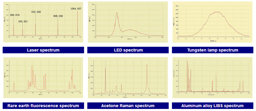
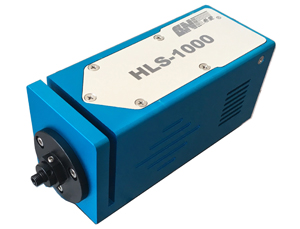
CNI fiber optic spectrometers with the characteristics of compact and portable design, plug and play, easy operation and Spectral Analysis 5.0 software downloads, can replace the old spectrophotometers. They are widely used in Laser wavelength and line width measurement and also the laser excitation fluorescence, Raman and LIBS spectrum measurement.
Fiber optic Spectrometer with the advantages of modularization and flexibility of its measuring system is widely used to measure wavelength and line width of laser, LED and common light source, can accurately obtain the spectral characteristics of the light source which is being tested. CNI developed spectrometers with the characteristics of compact and portable design, plug and play, easy operation and Spectral Analysis 5.0 software downloads, which are extensively applied on the fields of scientific research, teaching, industries and many other applications. CNI can also customize the wavelength and resolution of the spectrometers according to different customers` demands.
|
|
|
|
|
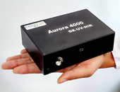
High Resolution Spectrometer
Aurora 4000
|
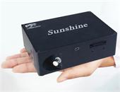
High Sensitivity Spectrometer
Sunshine
|
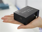
Compact Spectrometer
Firefly 4000
|
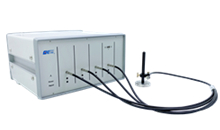
Multi- channel Spectrometer
Rainbow series
|
|
Resolution is up to 0.1nm (FWHM)
Application: Laser wavelength
analysis; LED sorting; Chemical,etc
|
Quantum effciency is up to 80%
Application:Raman spectrum;
Semiconductor processing, etc
|
Compact and portable design
Application: Laser wavelength
analysis; Biochemical analysis, etc
|
That is made features of wide
spectral rang and high resoultion,
with synchronous delay device
|
Components & Accessories
Sample Spectrum
